Buse BS100 IoT
May 1 2023At last year's OpenAlt conference, during a talk by Tomáš Tichý, I learned that DPMB is selling old onboard computers from buses and trams. They were being sold at a very cheap price, and I immediately knew I had to have one. The idea was to keep it on my desk and use it to control lights and other devices in my flat. I placed an order the same day, and the following workday it was ready for pickup.
At home, before taking it apart, I wanted to try getting it running. The only source of information I could find online about the computer seems to be http://jakub-svec.eu/clanek.php?clanek=BS100. The website provided specifications for the power wiring and indicated a voltage of 24V. Unfortunately, my homemade power supply could only provide 19V. Fortunately, the label on the computer itself stated a voltage range of 16-32V, so I was able to play with it. Using the service password mentioned on the website, I accessed the service menu and found the ID of the bus the computer came from: 2658 (https://www.bmhd.cz/evidence-dpmb/vuz.php?id=45452).
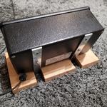
On the inside, I found much more stuff than I expected. But it makes sense; the computer needs to communicate with all kinds of devices over various interfaces. The main controller seems to be a 16-bit TOSHIBA microcontroller, TMP96C141BF. Even though it could be reprogrammed, it was much easier to replace it, including all the other circuitry. Thankfully, all the PCBs were connected with headers, so no work was needed, and I was left with the keypad, display, and case.
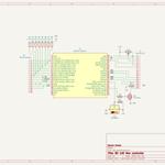
Reverse engineering the keypadFrom the start, I wrongly identified pin 14 on the connector as 5V and pin 16 as ground. This made it very difficult and confusing to figure out how the LEDs under the buttons were wired. After a while, I gave up on that and instead tried to buzz out the pins for the buttons and figure out the matrix circuit. That turned out to be very simple but a little bit time-consuming. After that, I returned to the LEDs. I identified all the remaining components on the board and found how they are connected, and then it all clicked together, and I finally realized my mistake from the beginning. Later, I found that pin 16 is a 1-wire bus for the Dallas Key. Here, you can see the final schematic.
New BrainFor the new microcontroller for the computer, I wanted to use Raspberry Pi Pico W. But at the time, it wasn't available, so I looked for a different microcontroller with Wi-Fi and MicroPython support. I decided on ESP-WROOM-32, which is very similar to Raspberry Pi Pico W but has double the RAM. By the way, Espressif was a partner of last year's OpenAlt, so I'm not sure if my selection is a coincidence or marketing at work.
The design of the board that connects everything is quite simple, with only a few parts. A MOSFET and resistor are used for controlling the LCD backlight, a potentiometer for LCD contrast, level-shifters to provide 5V logic to the LCD, and pull-down resistors for the keypad. I had to include those because some of the pins on the ESP-32 don't have internal pull-downs. In the spirit of the project, I tried to reuse as many parts as I could. This made it a little more challenging, for example, the 10-year-old prototyping board didn't really want to take solder very well, even after cleaning it. And for the life of me, I couldn't get the original LCD working. That's the reason why I included the level-shifters (some LCDs may not recognize 3.3V logic while being powered by 5V), but that didn't help. My best guess is that the LCD has some weird controller that only supports 8-bit communication. But I didn't test that and replaced it with a new one. When I was basically done, I decided to add a temperature sensor. I selected one that was quite cheap and communicated over OneWire. Thanks to that, I accidentally found out what the weird device on the computer's keypad was. It was a Dallas Key or iButton, a small ID device that uses OneWire with parasitic power, so it just needs two contacts (data and ground). I could have easily connected it to the same OneWire bus, but I didn't because I have no use for it.
SoftwareEven before I took the computer apart, I started prototyping the software with an old 1x16 LCD, which I suspected had the same interface, and tried out all the MicroPython libraries I would need for the project. That went very well, thanks to the Thonny IDE. It can interface with the REPL running on the ESP as if it were a local Python interpreter and also allows browsing files on the ESP's flash.
When I started writing actual code, things didn't go well for very long. I started with code for Wi-Fi, display, reading the keypad, and laying the foundation for the menu system. But then I got stuck at communicating with the Deconz IoT gateway via the REST API. I used the built-in urequests library. The problem was that it only reads from the socket until some timeout runs out, which is about 4 minutes. The urequests library doesn't use the Content-Length header (Deconz fails to set it correctly anyway), and the socket implementation on ESP-32 doesn't seem to support setting a custom socket timeout. So I had to rewrite urequests, and while I was at it, I made it into a context manager.
Another setback happened when I created a library and interface for controlling lights. The issue was that I only tested it with one light. Turns out there are two ways to define the color of a light in the Zigbee protocol: 'hsv' and 'xyz'. Not all lights support 'hsv', which was a problem because my code relied on it. So I had to find out how to convert between those two. The algorithm was a bit over my head (math isn't my strong point), but fortunately, I found the code I needed in some JavaScript library. I had to simplify it and select some magic numbers. It seems that the controlling device is supposed to correct for the color inaccuracy of the lights, something I don't do. It makes the code simpler, but the color selection is less precise. In the end, my code for light control is far from perfect, but it is good enough for my needs.
After the issue with the lights, the rest of the code was easy. To utilize the display, I decided it would be nice if it could show me my calendar. Google has a nice API for that, but I didn't use it. The authentication is way too complicated for a device like this. Instead, I used the Google Apps Script service. There, I wrote JavaScript code that takes the next three events in my calendar and makes them available on some URL with only a secret token string as authentication. As a bonus, it formats the data so the device can directly print it to the screen. Then I added temperature and time display (time is synchronized over NTP), light presets, service menu, and that was it.
Features- Main screen: Shows the next three events in my calendar with time (if it is today's event) or date, current temperature and time. When you are on the main screen, the backlight of the display and keypad is turned off after some time, pressing any key will turn it back on. Direct light control: From the main screen by pressing [POTVRZENÍ], you get a list of all available lights (or sockets). From this list, you can either press [REVIZE] to turn on/off the light or [POTVRZENÍ] again to get to the color menu for the selected light. There you can set the color temperature or hue/saturation color and brightness, button [REVIZE] is switching between these two modes. The menu is navigated with up/down double arrows and values are changed with left/right arrows, by pressing up arrow the selected values are sent to the light. Finally the values can be confirmed with [POTVRZENÍ] or you can exit the menu with button [ZRUŠENÍ] and previous light state will be restored.
- Presets: Groups of light states that can be quickly applied by pressing buttons [1] - [9], or selected from list that is accessed by pressing [KÓDOVÁ ZPRÁVA]. If you press the red button and then the number for some preset all the lights in the preset will be turned off. Using presets you can for example set all lights in a room to your favorite color or turn on multiple power sockets at once with the press of single button and then turn them all off.
- Service menu: You get there by pressing the [SERVIS] button. There you can see IP address of the device, toggle daylight saving time and configure presets with [REVIZE] button and configure presets. In the Presets menu you can add/remove lights from preset groups, change light states for each preset and name the preset groups.
In the end, I'm very pleased with the result, except for the issue with urequests and REST API that slows down communication with deconz. However, I'm confident that I will fix that sooner or later. This DIY device has become the most convenient method for controlling lights and smart sockets in my home, alongside dedicated Zigbee switches. The entire project is open-source, and you can find all the code and hardware schematics on my GitHub page.
https://github.com/velezd/BS100-IoT


